

What should be checked before an AEM electrolyzer stack leaves the factory?
For equipment buyers and system integrators, a specification sheet is only the starting point. The next questions concern the actual unit being delivered: what was tested, under which conditions, against which acceptance criteria, and with what results?
Factory Acceptance Testing, or FAT, turns agreed requirements into documented evidence of the equipment’s condition before shipment.
FAT establishes whether the tested equipment meets agreed requirements under specified conditions. It does not, by itself, demonstrate long-term service life or constitute third-party certification.
Establishing the acceptance basis
AEM water electrolysis can draw on testing practices developed for other electrolyzer technologies. However, acceptance limits must reflect the selected materials, stack design, operating conditions and scope of supply.
ISO 22734-1:2025 provides a safety framework for hydrogen generators using water electrolysis. Applying that framework to a particular project requires identifying the relevant requirements and distinguishing the stack from the complete hydrogen production system. Reference: ISO 22734-1:2025
Before testing begins, the FAT plan should identify the equipment, procedures, conditions, acceptance criteria and required records. The following four areas provide a practical framework for reviewing that plan.
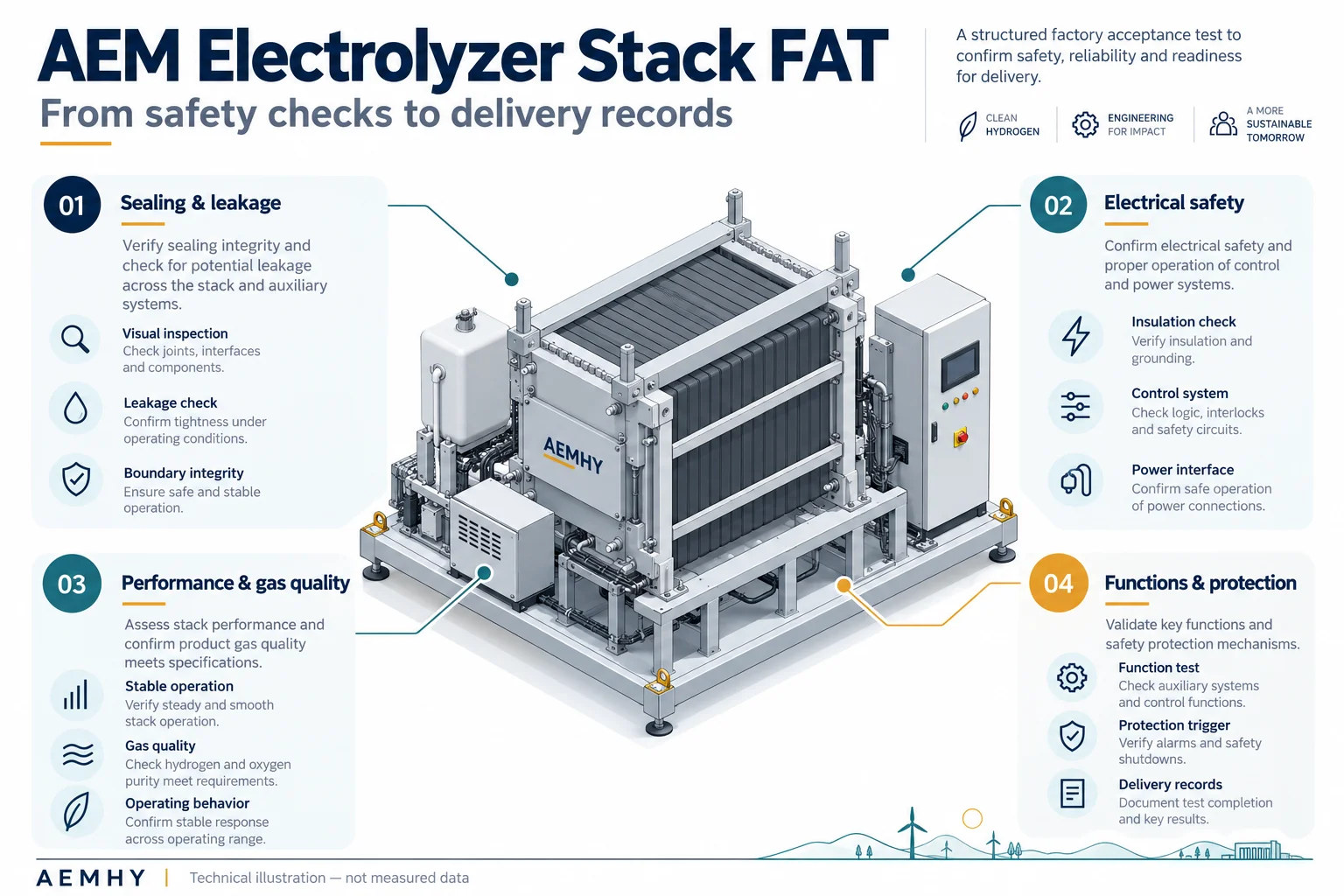
1. Sealing and leakage checks
Sealing checks assess the integrity of the stack, connections and relevant components under defined test conditions.
Depending on the design and approved procedure, testing may include pressure-hold or pressure-decay measurements and local leak detection. External leakage and unintended leakage between internal circuits should be distinguished.
The test medium, pressure, permissible differential pressure and acceptance limits must be appropriate for the equipment and applicable requirements. Testing should be performed by qualified personnel using approved procedures.
A useful report records more than “leak test passed.” It identifies the method, conditions and basis for acceptance.
Sealing integrity and operational gas crossover are different issues. Passing a leak test does not establish that hydrogen and oxygen crossover through the membrane is absent under every operating condition. Gas quality, monitoring and protective measures require separate consideration.
2. Electrical safety checks
Electrical verification should match the delivered equipment and its interfaces.
Depending on the configuration and applicable requirements, checks may include insulation resistance, protective bonding continuity and dielectric withstand testing where required. The test plan should distinguish design or type verification from routine checks performed on individual units.
For a stack-only delivery, the report should also identify which results relate to the stack itself and which relate to the power supply, control cabinet or test facility.
A result obtained on a factory test bench should not be presented as acceptance of the customer’s complete installed system.
3. Electrochemical performance and gas quality
Performance data become useful when the operating conditions and measurement boundaries are clear.
Polarization behaviour and cell-voltage distribution
Measurements across the agreed operating range help characterize the relationship between current and voltage. Individual cell-voltage measurements can help identify uneven behaviour and conditions requiring further investigation.
Temperature, pressure, electrolyte conditions, flow and stabilization time should accompany the results because they influence the measured performance.
Hydrogen output and specific energy consumption
Before comparing energy figures, establish what the measurement includes.
Stack DC consumption and complete-system AC consumption are different metrics. System consumption may include power conversion, water treatment, circulation, cooling, drying and other auxiliary equipment.
Values expressed in kWh/Nm³ should identify the reference temperature and pressure for gas volume, the moisture basis, and the operating load. The European Commission’s Joint Research Centre provides harmonised testing guidance intended to support meaningful performance comparisons. Reference: JRC water electrolysis testing protocols
Gas quality and additional diagnostics
Gas-quality results should identify the sampling location, wet or dry basis, analytical method and relevant impurities. Measurements at the stack outlet and after downstream drying or purification describe different conditions.
Where included in the agreed test plan, electrochemical impedance spectroscopy, or EIS, can provide additional diagnostic information about resistance and interfacial behaviour. Its interpretation requires supporting evidence; a single EIS measurement does not establish membrane health or service life.
EIS should therefore be identified as a specified diagnostic activity rather than assumed to be a universal routine acceptance test.
4. Functions and protective responses
A project may also require checks of start-up, shutdown, load changes and protective responses.
Where the test configuration includes the relevant controls and auxiliary equipment, approved procedures can verify functions associated with overpressure, excessive temperature, overcurrent and emergency shutdown.
These checks should use safe, controlled methods or fault simulation. The report should state which functions belong to the stack, which depend on the test platform or complete system, and which require verification after installation.
Successful factory testing does not remove the need for commissioning and any agreed site acceptance testing.
What should a useful FAT report contain?
Buyers should look for six elements:
Equipment identification: model, serial number, configuration and scope of supply.
Test conditions: temperature, pressure, load, process medium and test duration.
Measurement boundaries: stack or system, DC or AC, and gas-sampling location.
Acceptance criteria: methods, agreed limits and applicable documents.
Instrumentation: key instruments, calibration status and relevant uncertainty information.
Results and follow-up: measured values, deviations, corrective actions and retest records.
Together, these details help the buyer assess whether the results are relevant to the intended application. They also provide a reference for subsequent commissioning, operation and maintenance.
Discussing acceptance requirements with AEMHY
Agreeing on the test scope early helps suppliers and customers establish a shared technical basis for delivery.
When discussing an AEM electrolyzer project with AEMHY, provide the required hydrogen output, delivery pressure, gas-quality requirements, power supply, operating profile and integration scope. The required acceptance activities and documentation can then be discussed for the selected configuration.
A useful FAT report explains what was tested, how it was tested, what the results were, and which conclusions those results support.
Visit the AEMHY website to discuss stack selection and project acceptance requirements.